Graphing a Modified Goodman Diagram in Excel - Simplified Guide
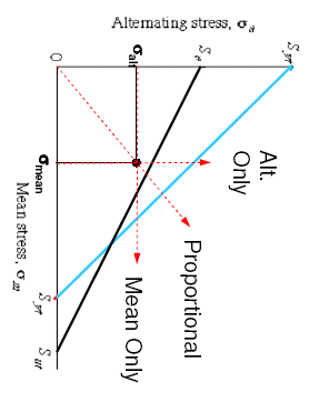
When dealing with fatigue analysis in mechanical engineering, the Modified Goodman Diagram provides invaluable insight. By plotting mean stress against alternating stress, engineers can evaluate the fatigue strength of a material under varying load conditions. Here's a simplified guide on how to graph this important tool using Microsoft Excel:
Preparation
Before we jump into graphing, ensure you have the following:
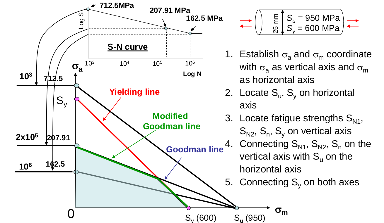
- The Ultimate Tensile Strength (Sut) of the material, which will be our reference point on the fatigue life.
- The Fatigue Strength (Se) or endurance limit, which represents the stress level at which the material can withstand infinite cycles.
- The Yield Strength (Sy), for defining material limits.
Steps for Graphing in Excel

1. Input Your Data

- Create headers in Excel: Column A for Mean Stress (σm), and Column B for Alternating Stress (σa).
- Input your Sut, Se, and Sy values in appropriate cells, preferably near your graph area.
2. Calculate Modified Goodman Line
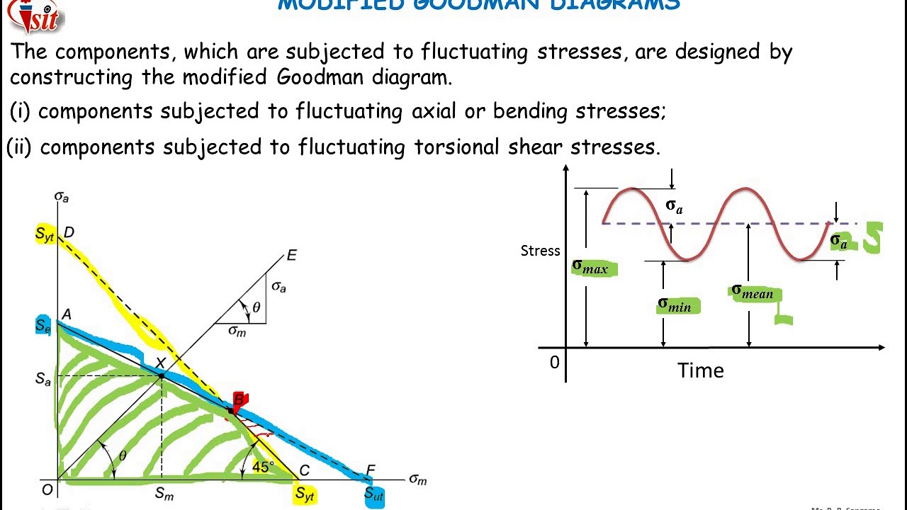
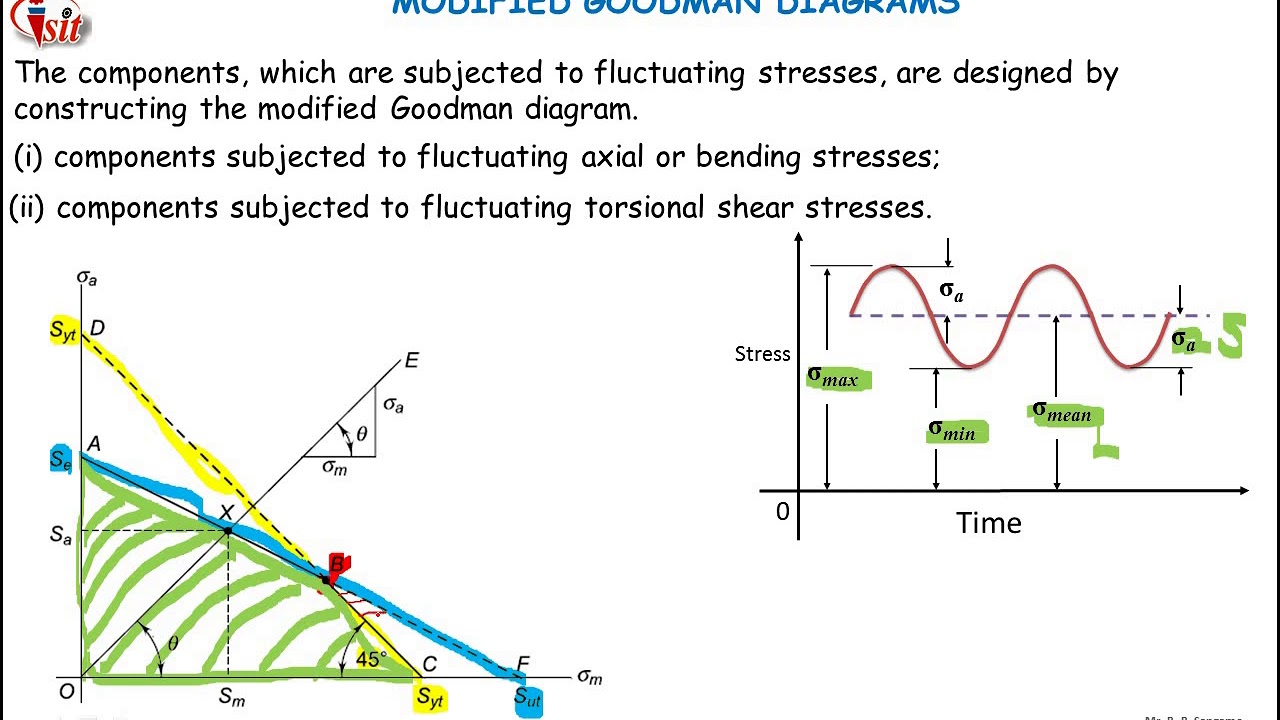
- Use the formula σm + σa = Sut to define the Modified Goodman Line.
- This line essentially shows where mean stress plus alternating stress equals the ultimate tensile strength, where the component would fail in one cycle.
3. Plotting the Graph
- Select your mean stress (σm) data, hold down the control key (Windows) or command key (Mac), and select your alternating stress (σa) data.
- Go to Insert > Scatter and choose the scatter plot without lines.
4. Adding the Goodman Line

📝 Note: You’ll need to manually add points or use a chart formula for a more precise curve.
- Add a line from (Se, 0) to (0, Sut) to represent the Goodman Line.
Point σm (Mean Stress) σa (Alternating Stress) A 0 Sut B Se 0 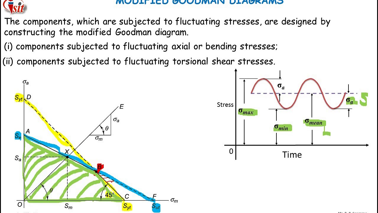
- Use the ‘Add Chart Element’ option to manually draw this line.
5. Enhance Your Graph

- Label your axes with units, ensuring they’re readable and properly scaled.
- Add a title to your graph like “Modified Goodman Diagram for [Material]”.
- Include gridlines if they aid visibility.
6. Interpreting the Graph
Once plotted, here’s how to interpret:
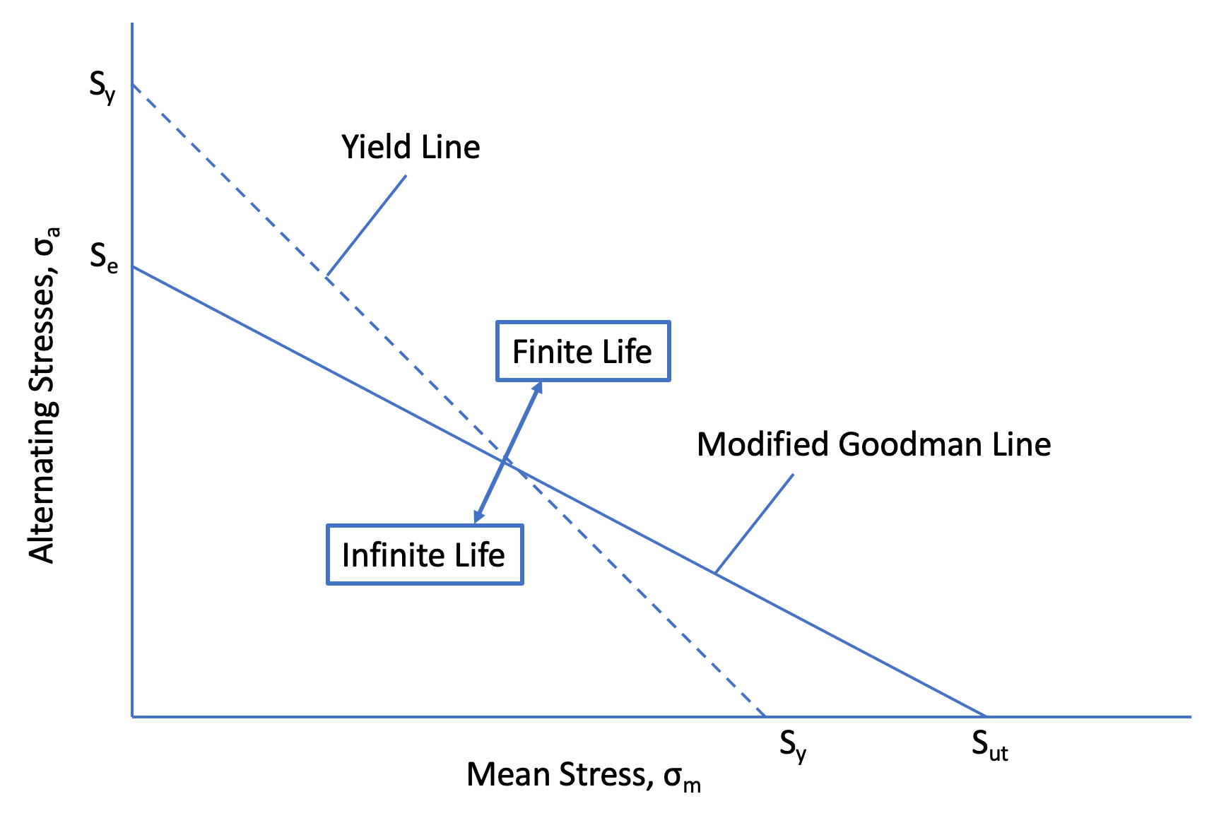
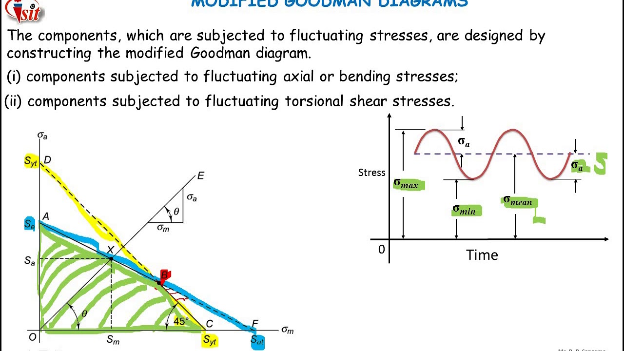
- Points within the Goodman Line and Yield Line indicate safe operating conditions.
- Points outside these lines suggest the material is at risk of fatigue failure.
Finalizing your graph, you'll have a visual representation of your material's fatigue life, which is crucial for designing parts that need to endure repeated loading:
Wrapping up, this guide has outlined the steps to effectively graph a Modified Goodman Diagram using Excel, which is key for understanding the fatigue strength of materials under cyclic loading. Remember:
- The preparation phase ensures your data is ready for plotting.
- Calculations and plotting steps require careful attention to detail for accuracy.
- Correctly interpreting the graph allows for better design decisions, keeping safety in mind.
Why use a Modified Goodman Diagram over S-N curves?

+
A Modified Goodman Diagram provides a broader view of fatigue behavior under various stress conditions. It accounts for both mean and alternating stresses, allowing for a comprehensive safety assessment that S-N curves, focused solely on stress cycles, might not capture as effectively.
What are the limitations of the Modified Goodman Diagram?

+
The Modified Goodman Diagram assumes linear stress amplitudes, which might not always reflect real-world variable amplitude loading. Additionally, it can be overly conservative, especially when dealing with materials that don’t show significant variability in fatigue properties.
How can I account for surface finish or temperature effects?
+
These factors can modify the fatigue properties. Surface finish can be adjusted by altering the endurance limit (Se) using correction factors provided in material data sheets, and temperature effects can be accounted for by adjusting the material’s properties to reflect elevated or reduced temperature conditions.
